calebharry
Member
- Joined
- Sep 30, 2013
- Messages
- 11
- Reaction score
- 0
Hey guys!
(btw excuse my typing mistakes im usually very good but the laptop im using at the moment is old and the keyboard is a bit stuffed)
First time posting on this forum, so give me a break if im a bit of a dummy when it comes to some things, plus im only 15
I recently aquired a custom mini chopper, made by some company in New Zealand (where i live) called MoFo, this company has gone out of buisiness, and i cannot find ANY info on my chopper anywhere, any info is right here infront of me (being the bike itself)
I can see it has a lot of chinese parts, but it has a 110cc 4-Stroke engine, i have no idea if it has gears, if it does it will be a automatic because there is no clutch and no gear lever... I need a VERY BASIC wiring diagram for someone to draw out for me, i will post some pictures of different items on the chopper for you to try and help...
I have NEVER sen this runing and neither did the owner before me, to be honest i think it was stolen, because when i got it several wires had been cut and spliced ect.
I believe this bike used to be road legal, considering it has a headlight, and did have indicators, brake light, and it does have a horn.
All i care abut is getting this bike going, i would like if the headlight worked, but if not thats fine, getting the bike running is the first step, the fuel tank on the bike, had a key to open it to refill, but because i dont have any keys, i spent 4 hours yesterday drilling and smashing it to try get it to open, eventually i did, and sort of fixed it so now it can be locked and unlocked, but now with any key, that was one big problem, because i wouldnt have been able to put fuel in te bike, but now thats fixed
About the engine, and geting that running, i looked for a wiring diagram online and found one on this website for a Loncin? 110cc mini chopper, so i thought, sweet, that'll work! And i was following that, untill i got to the wires that go into the engine itself, in the diagram, it had only 2 wires going to the engine, but my bike has 5 wires, my flatmate suggested that maybe it has automatic gears, (the bike does have some sort of coil-thing inside the engine) possibly that coil was linked to those wired and sensed when to change gears?
So i have a kill switch (i believe) on the handle bars, with 2 wires coming out of it, (on the same handle-switch assembly, it had headlight controls and hazard light controls - i cut all of these wires off consideing i dont need them (theyre long enough to splice and solder back together if needed))
Then folowing those 2 wires, one wire is Yellow with red stripe, the other WAS light green but been spliced to a black wire (goes to the same place) these wires go to a plug, and out the other side comes a Red/White wire, and a Yellow/Green wire
Following the Yellow/Green wire, it splices off and goes in two different directions, both handlebar switches for the brake light (one on each side) the wires go through the brake switch and come out as a Black wire, the two black wired then join back together and go through another plug into what i believe was the Key Barrel? (i included a picture of the back with different wires so you can tell me where to go from there)
Following that White/Red wire from the kill switch, it goes through a plug and turns into a Yellow/Red wire and then goes into a round thing (pictured, looks like a huge metal capacitor?)
Two big wires then come out of that round thing, one goes to the battery (red wire, positive) and the other goes to the starter motor.
Out of the starter comes a Black wire, and a Green wire (both same current/ starting place) the Black wire goes to the negative of the battery, and the Green wire looks like a ground because it goes to a lot of different places,
-That big capacitor thingy (connected to battery and starter motor)
-A 4 pin box thing under the seat
-The key barrel
-Into the engine
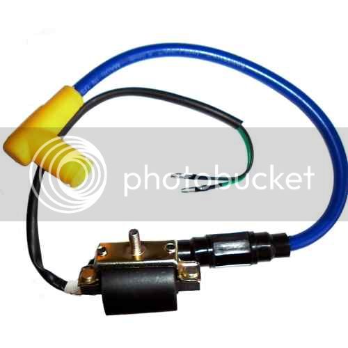
-Under the fuel tank, goes into a black round thing which makes the spark for the spark plug
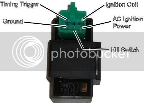
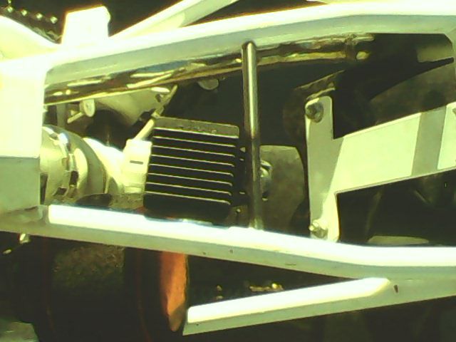
-Another box under the fuel tank, has 5 wires (including green) going in/coming out of it, i believe this is the CDI?
-Into a 3 pin plug that looks like it could charge the battery?
-Into the headlight...
And a lot of other places, petty much every other plug on the bike, if you need to know, ask, and ill happily tell you.
And yeah, thats about it i think, Any help here you can give me will be much apreciated!
All i want is for the bike to be running, thats all i care about, So tel m what i need to do!


The 2 killswitch wires

The 3 pin charging plug? and the spark plug generator thing...

As you can see, i have a lot of wires to deal with (thats only about 1/2)

The Key Barrel?

Back of Key Barrel (note black wire, bottom right under red)

The big metal capacitor thing, connects to battery and starter motor (two big red wires) the black wire (actually is a cover for 2 wires, i noted them earlier)

BIG MESS!!! HELP MEE!!! (more confusing than it looks)

Any help please! Thanks!
(btw excuse my typing mistakes im usually very good but the laptop im using at the moment is old and the keyboard is a bit stuffed)
First time posting on this forum, so give me a break if im a bit of a dummy when it comes to some things, plus im only 15
I recently aquired a custom mini chopper, made by some company in New Zealand (where i live) called MoFo, this company has gone out of buisiness, and i cannot find ANY info on my chopper anywhere, any info is right here infront of me (being the bike itself)
I can see it has a lot of chinese parts, but it has a 110cc 4-Stroke engine, i have no idea if it has gears, if it does it will be a automatic because there is no clutch and no gear lever... I need a VERY BASIC wiring diagram for someone to draw out for me, i will post some pictures of different items on the chopper for you to try and help...
I have NEVER sen this runing and neither did the owner before me, to be honest i think it was stolen, because when i got it several wires had been cut and spliced ect.
I believe this bike used to be road legal, considering it has a headlight, and did have indicators, brake light, and it does have a horn.
All i care abut is getting this bike going, i would like if the headlight worked, but if not thats fine, getting the bike running is the first step, the fuel tank on the bike, had a key to open it to refill, but because i dont have any keys, i spent 4 hours yesterday drilling and smashing it to try get it to open, eventually i did, and sort of fixed it so now it can be locked and unlocked, but now with any key, that was one big problem, because i wouldnt have been able to put fuel in te bike, but now thats fixed
About the engine, and geting that running, i looked for a wiring diagram online and found one on this website for a Loncin? 110cc mini chopper, so i thought, sweet, that'll work! And i was following that, untill i got to the wires that go into the engine itself, in the diagram, it had only 2 wires going to the engine, but my bike has 5 wires, my flatmate suggested that maybe it has automatic gears, (the bike does have some sort of coil-thing inside the engine) possibly that coil was linked to those wired and sensed when to change gears?
So i have a kill switch (i believe) on the handle bars, with 2 wires coming out of it, (on the same handle-switch assembly, it had headlight controls and hazard light controls - i cut all of these wires off consideing i dont need them (theyre long enough to splice and solder back together if needed))
Then folowing those 2 wires, one wire is Yellow with red stripe, the other WAS light green but been spliced to a black wire (goes to the same place) these wires go to a plug, and out the other side comes a Red/White wire, and a Yellow/Green wire
Following the Yellow/Green wire, it splices off and goes in two different directions, both handlebar switches for the brake light (one on each side) the wires go through the brake switch and come out as a Black wire, the two black wired then join back together and go through another plug into what i believe was the Key Barrel? (i included a picture of the back with different wires so you can tell me where to go from there)
Following that White/Red wire from the kill switch, it goes through a plug and turns into a Yellow/Red wire and then goes into a round thing (pictured, looks like a huge metal capacitor?)
Two big wires then come out of that round thing, one goes to the battery (red wire, positive) and the other goes to the starter motor.
Out of the starter comes a Black wire, and a Green wire (both same current/ starting place) the Black wire goes to the negative of the battery, and the Green wire looks like a ground because it goes to a lot of different places,
-That big capacitor thingy (connected to battery and starter motor)
-A 4 pin box thing under the seat
-The key barrel
-Into the engine
-Under the fuel tank, goes into a black round thing which makes the spark for the spark plug
-Another box under the fuel tank, has 5 wires (including green) going in/coming out of it, i believe this is the CDI?
-Into a 3 pin plug that looks like it could charge the battery?
-Into the headlight...
And a lot of other places, petty much every other plug on the bike, if you need to know, ask, and ill happily tell you.
And yeah, thats about it i think, Any help here you can give me will be much apreciated!
All i want is for the bike to be running, thats all i care about, So tel m what i need to do!


The 2 killswitch wires

The 3 pin charging plug? and the spark plug generator thing...

As you can see, i have a lot of wires to deal with (thats only about 1/2)

The Key Barrel?

Back of Key Barrel (note black wire, bottom right under red)

The big metal capacitor thing, connects to battery and starter motor (two big red wires) the black wire (actually is a cover for 2 wires, i noted them earlier)

BIG MESS!!! HELP MEE!!! (more confusing than it looks)

Any help please! Thanks!


![Bike Phone Mount Holder, [Camera Friendly] Motorcycle Phone Mount for Electric Scooter, Mountain, Dirt Bike and Motorcycle - 360° Rotate Suitable for iPhone & Android Smartphones from 4.5-7.0 inches](https://m.media-amazon.com/images/I/51ZirRrsA+L._SL500_.jpg)





![2 Pack Bike Phone Holder Mount [2024 Upgraded Gift Set]- 3S Easy Install, Motorcycle Phone Mount Universal Handlebar, Cell Phone Holder Fit for EBikes Electric Scooter Dirt, Bike Accessories for Adult](https://m.media-amazon.com/images/I/41JK0xwDupL._SL500_.jpg)


